
When modeling a finite state machine you might come to a point where you need to think about how to enter and leave your state machine's regions. In general, there are three structural elements available in YAKINDU Statechart Tools to define a particular entering, leaving and finishing behaviour for your state machine. These elements are called entry point, exit point and final state. A typical use case for a more fine grained entry and exit handling within a state machine might be error handling as an alternative to the default execution flow of a state machine.
Entry, exit, and final state
Entry
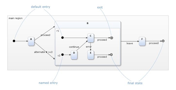
When a state machine starts or when the control flow enters a region, an entry defines which state will be activated first. An entry is a so called pseudo state, has just a single outgoing transition, no trigger and no guard condition. It is depicted as a filled circle, see figure "Entry, exit, and final state".
An entry without a name is called the default entry. It is similar to the UML's initial state. A region contains exactly one default entry. Additionally, YAKINDU Statechart Tools provide alternatives by named entry points, thus implementing different kinds of behaviour, depending on which entry point has been taken. If a region comprises multiple entries, these entries must be uniquely named within the region.
Entering a region explicitly via a named entry can be done by specifying a transition property on a transition leading into the surrounding state in the form: # > entry-name.
The state machine in figure "Entry state" depicts the usage of named entry points. The composite state Handle result contains a default entry as well as an entry named failure. The transition from state A to Handle result specifies that whenever an error event is fired, the Handle result state should be entered by its failure entry point which leads to the activation of Handle failure substate.

Entry state
Exit
An exit is a pseudo state that is used to leave and deactivate a composite state. Exits are the counterpart to entries. An exit may have multiple incoming transitions but never an outgoing one. It is depicted as an unfilled circle with an X-shaped cross, see figure "Entry, exit, and final state".
In contrast to the UML, YAKINDU Statechart Tools allows a region to contain multiple exits. Each exit must either have a name that is unique within its region or must be the one and only default exit. When an exit is reached, all states in other regions of the same composite state are deactivated immediately - In other words, reaching an exit in one of a composite state’s regions has severe consequences for all the other regions since they are exited, too.
If a region is left via a named exit, there must be an unguarded outgoing transition defining a transition property like # exit-point-1 > [ exit-point-2 > ] that catches the exit and thereby influences the execution flow on the outside.
Entries & Exits
The statechart in figure "Entries and exits" depicts how both pseudo states play together. It contains two composite states:
- The composite state Process models a process with two passes (states) A and B. If both passes succeed, the composite state is left via the no_problem exit node. However, if an error occurs in either A or B the execution flow proceeds to the problem exit point and leaves the composite state there.
- The composite state Handle result is intended to handle the processing result, be it success or failure. It has two entry points success and failure.
The question is how to connect the exit points of Process to the corresponding entry points of Handle result. The transition leading from Process to Handle result on the left specifies # no_problem> >success. This means: If the source composite state is left via the no_problem exit point, enter the target composite state at the success entry point. The specification of the transition on the right is analogous: If the source state is left via the problem exit point, enter the target state at the failure entry point. The order of exit and entry points in a transition specification is irrelevant. Instead, the position of the > character is decisive:
- If the > character is to the right of a name, like in exit_name>, that name denotes an exit.
- If the > character is to the left of a name, like in >entry_name, that name denotes an entry.
Alternatively, Process could have been modelled with two different error exit states, say error_1 and error_2. This would allow to respond differently to different error conditions, while still enabling to catch them both with a single flow. A transition with # >error_1 >error_2 problem> would do so.

Entries and exits
Final state
A final state denotes the end of the execution flow of a state machine or region and is depicted as an unfilled circle with a smaller filled black circle inside, see figure "Entry, exit, and final state". A final state can have multiple incoming transitions but no outgoing ones. Within a region, only one final state is allowed, but each region may have its own final state. Final states do not have any properties except for a name.
When a region reaches its final state, control stops there and waits until all other orthogonal regions, if any, have reached their respective final states, which is the major difference to exits. This also means that final states are proper states in the meaning that they can be active, whereby entry and exit points are pseudo states; they are only used to connect states across region boundaries.

Comments