Computer science is about solving specific tasks with the help of computers or computer-controlled systems. Examples might include the creation of a railway timetable, the visualisation of neutron fluxes, the distribution of power in a nuclear reactor, the simulation of physical processes in semiconductor components, the implementation of a social media app or the development of machine control systems of various types.
A model of what is to be implemented in software should be available before programming begins. A model is a simplified representation of reality, and excludes everything that is irrelevant to the task to be solved. In a control system for a coffee machine, for example, the fill level of the beans is important, while the colour of the coffee cup or the gender of the operator is not.
The model should be clear and easy to understand, and through sensible structuring even complex interrelationships can be managed. Comprehensible models are important, not only for software architects and developers, but also for their clients, i.e. departments and customers. If a model is comprehensible, the client can use it to determine whether the developers have understood the task correctly. Mistakes and misunderstandings can be clarified before any effort is wasted in implementing an incorrect solution.
Some tasks can be described particularly well with the aid of state machines. Computer science students may learn state automatons as deterministic automata, finite state machines, Moore, Mealy, Harel automata or the like in theoretical computer science – but not infrequently question marks remain on their faces, as if to say “What is that supposed to be?”
Automatic state machines: no mere theory
Automatic state machines are suitable for describing so-called “event-discrete systems”. The idea here is that a system is always in exactly one of a finite number of states. For example, a light switch is always in one of two states, "On" or "Off". State transitions define from which states other states can be reached and under what conditions each state transition occurs.
Before this discussion becomes theoretical, let's look at a concrete example: a control system for a blind. In the simplest case, this has three states:
- The blind is not moving (state idle).
- The blind is moving upwards (state Moving up).
- The blind is moving downwards (state Moving down).
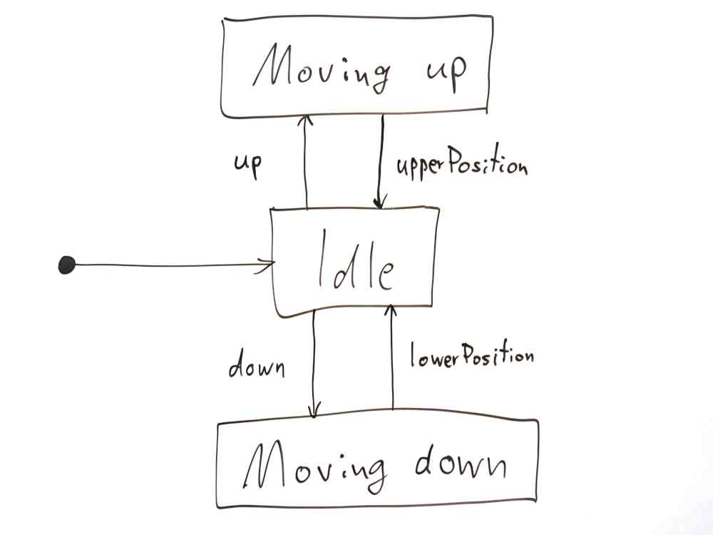
In the state diagram, states are represented as rectangles with rounded corners, and state transitions as arrows, as shown in Figure 1:

The point on the left indicates the initial state of the machine, Idle. If the user presses the [↑] key, the up event is created, the automaton changes to the state Moving up, and the blind moves upwards. As soon as it reaches the upper position, the position sensor generates the event upperPosition. This creates the transition state, the transition from Moving up to Idle. Closing the blind works analogously when the user presses the [↓] button. The state diagram illustrates the dynamic behaviour of the system.
The model, however, is still imperfect. We want to be able to position blinds not only fully open or fully closed, but also at intermediate positions. In addition, the blind should automatically close when there is strong sunlight, and it also ought to be possible to control the blind manually. In addition the blind should always be raised in strong wind to avoid damage. Users should not be able to override this feature: it should not be possible to lower the blind until the wind has decreased. It may also be required to raise and lower the blinds at specific times.
Modeling state machines using the blind control as an example
We want to model some of these functions with the help of an automatic state machine rather than a pencil and a whiteboard, so we need a capable modeling tool. In the following example we used YAKINDU Statechart Tools. This is Eclipse-based and supports, not only the modeling itself, but also dynamic simulation of the model and generation of the state machine as source code in various programming languages. This is discussed later.
First we will convert the whiteboard model step by step using YAKINDU Statechart Tools. If you want to try this for yourself, you can download the software, an installation guide and a five-minute tutorial].

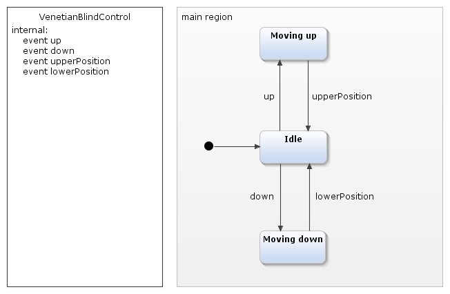
Modeled with this tool our blind control example looks like this:

The definition area, which defines the names of events, has been added.
To stop the blind on the way up or down at the current position, the user presses the button that is opposite to the respective movement, for example, [↓] when the blind is moving up.
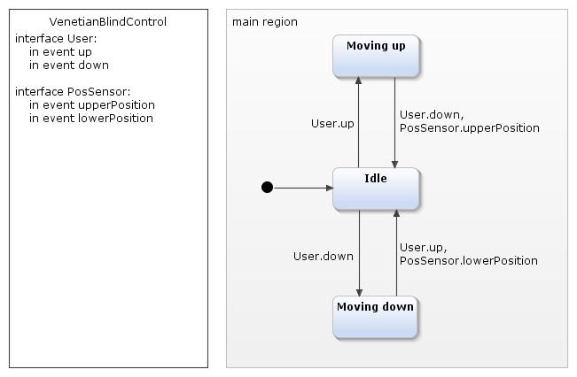
The corresponding extended model looks like this:

There are now two possible events instead of one, which lead from of the states of movement into the rest state. Commas next to the transitions separate their names.
At the same time we have made a clear distinction between events that are triggered by the user and those by the position sensor of the blind. YAKINDU Statechart Tools refers to these as interfaces. The definition area determines which interfaces exist and which events are assigned to them. In our case this is the user interface with the events up and down, as well as the interface PosSensor with the events upperPosition and lowerPosition.
Conditional state transitions with variables and guard conditions
Let’s now introduce prevention of storm damage to the blind. For this purpose the blind has a wind speed sensor that provides values between 0 (no wind) and 100 (the maximum value of the sensor).
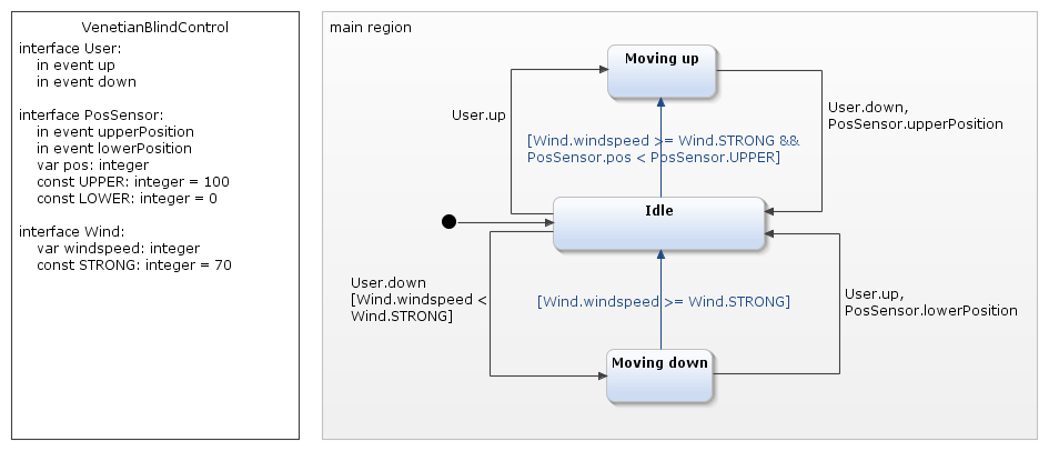
In the state machine the wind speed is available in the windspeed variable of the Wind interface. To keep the example simple we will not go into how the wind speed is transferred to the variable. The Wind interface also contains the constant STRONG, which indicates the speed at which the wind is strong enough for the blind to be raised.
There is now an additional transition (the blue arrow) from the state Moving down to the state Idle. This is provided with a condition, "Wind.windspeed >= Wind.STRONG". This guard condition is enclosed in square brackets, and ensures that the transition is executed only if the condition is met. A further transition leads from Idle to the state Moving up, but only if the blind – as determined by the position sensor – is not already up. To make this information available the PosSensor interface is extended accordingly.

The "blue" transitions in the state diagram thus ensure automatic raising of the blind. Now we just have to prevent the user from moving the blind down again. On the transition Idle → Moving down the guard condition "Wind.windspeed < Wind.STRONG" assigned to the User.down event ensures this.
For the transition Moving up → Idle, however, this is not quite so simple, as it should be executed at the PosSensor.upperPosition event in any case. However, the guard condition always refers to all the events mentioned, so would not be useful here. The correct solution is to split the transition into two individual transitions: one transition takes care of the event User.down and contains the guard, the other takes PosSensor.upperPosition without any additional condition to the Idle state.
We could now introduce a light sensor and, as described above, with its help automatically move the blinds down when it is very bright outside. This is, however, more tricky than in the case of strong wind, because the user can override that and move the blind up again. In this case, the automatic has to hold back and not shut down the blind again – at least not immediately. I will discuss this topic in another blog post, as well as interactive state machine simulation and the generation of Java, C or C++ source code. This saves us not only from manual programming, but also from the errors that are typical incurred.
To read the whole “How to use state machines for your modeling” series, download our whitepaper for free.


Comments